Electric Circuit Diagram
When you look at an electric circuit diagram, you’re actually peeking into the heart of how electrical devices work. Imagine having a clear map that shows exactly how power flows from a battery, through wires, switches, and loads like bulbs or motors, and back again.
Understanding this map can make all the difference when you want to fix, build, or simply grasp how your gadgets come to life. You’ll learn how to read and draw electric circuit diagrams with ease, discover the meaning behind common symbols, and gain the confidence to follow the flow of electricity yourself.
Ready to unlock the secrets of electric circuits and take control of your projects? Keep reading to master the basics and beyond.

Credit: www.youtube.com
Basic Circuit Parts
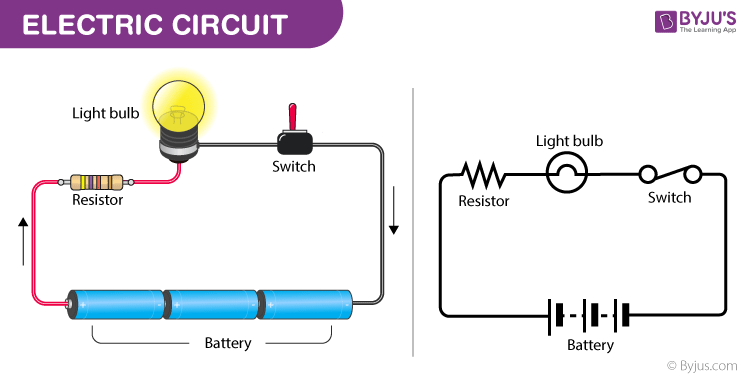
An electric circuit diagram shows how electrical parts connect. Every circuit has basic parts. These parts work together to make electricity flow. Understanding them helps you read or build circuits easily.
Each part has a special role. They form a path for electric current. The path must be complete for the circuit to work. Let’s explore the main parts of any electric circuit.
Power Source
The power source gives energy to the circuit. It pushes electrons to move through the wires. Common power sources include batteries and power supplies. Without a power source, no current flows.
Conductors
Conductors are wires that carry electric current. They connect all parts of the circuit. Usually, conductors are made of copper or aluminum. Good conductors have low resistance to help current flow easily.
Load Devices
Load devices use electrical energy and change it into light, heat, or motion. Examples are light bulbs, motors, and heaters. The load is where the circuit’s energy is used or consumed.
Control Switches
Control switches turn the circuit on or off. They open or close the path for electricity. Switches help control when devices work. They make circuits safe and easy to use.
Credit: byjus.com
Common Circuit Symbols
Electric circuit diagrams use common symbols to represent parts clearly and simply. These symbols help anyone read and build circuits without confusion. Understanding these symbols is the first step in learning about electronics. The symbols show wires, switches, power sources, and loads in a neat, universal language.
Wires And Connections
Wires in diagrams are shown as straight lines. They connect different parts and carry electric current. When two wires cross without a dot, they do not connect. A small dot shows a junction where wires join. Correctly reading these connections is crucial to understanding the circuit.
Switch Symbols
Switches control the flow of electricity. The common symbol is a break in a line with a small arm that can open or close. Open means no current passes; closed means current flows. Different switches have variations but share this simple idea.
Power Source Icons
Power sources provide energy to the circuit. Batteries are shown as a pair of lines, one longer (positive) and one shorter (negative). Other sources like generators may have unique symbols. Recognizing these icons helps identify where the circuit gets its power.
Load Representations
Loads use electrical energy to do work. A light bulb looks like a circle with a filament inside. Motors, resistors, and other devices have their own symbols. Loads show where the energy is used, making the diagram easy to follow.
Types Of Circuit Diagrams
Electric circuit diagrams show how electrical parts connect and work together. Different types of circuit diagrams serve distinct purposes. They help electricians, engineers, and hobbyists understand and build circuits easily. Knowing the types of diagrams improves your ability to read and create circuits.
Wiring Diagrams
Wiring diagrams display the physical connections of wires in a circuit. They show where wires connect to devices like switches and outlets. These diagrams are simple and focus on actual wire paths and colors. They help in installing or repairing electrical systems.
Schematic Diagrams
Schematic diagrams use symbols to represent components and their connections. They do not show real wire layouts but focus on the circuit’s function. These diagrams are easier to follow for understanding how a circuit works. They are common in electronics and engineering fields.
Block Diagrams
Block diagrams break down a circuit into main parts or blocks. Each block represents a section of the circuit with a specific function. This type of diagram gives a big-picture view without showing all details. It helps to understand the overall design and flow of the circuit.
Reading Circuit Diagrams
Reading circuit diagrams is essential for understanding how electrical systems work. These diagrams show the path electricity takes and the components involved. They use symbols to represent parts like batteries, resistors, and switches. Learning to read them helps you troubleshoot and build circuits effectively.
Start by focusing on the flow of power, then identify each component. Next, understand how components connect and interact. Finally, follow the control paths that regulate the circuit’s operation.
Tracing Power Flow
Tracing power flow means following the path electricity takes. It starts at the power source, usually a battery or supply. The current moves through wires and components. Notice how the flow continues until it returns to the source. This path forms a complete loop, which is vital for the circuit to work.
Identifying Components
Components have specific symbols in circuit diagrams. A battery is shown as a pair of lines, one longer than the other. Resistors look like zigzag lines. Switches are drawn as breaks in the wire with a lever symbol. Recognizing these helps you understand the circuit’s function.
Understanding Connections
Connections are shown by lines linking components. A dot at a crossing means wires connect. If lines cross without a dot, they do not connect. This distinction is crucial to avoid confusion. Correctly reading connections shows how current flows between parts.
Following Control Paths
Control paths include switches or relays that start or stop power flow. Trace these paths to see how the circuit turns on or off. Switches open or close the circuit, controlling the current. Understanding control paths helps you grasp the circuit’s operation and safety features.
Drawing Circuit Diagrams
Drawing circuit diagrams is a key step in designing and understanding electrical circuits. These diagrams show how components connect and interact. They make building and troubleshooting circuits easier. Clear diagrams help communicate ideas effectively.
Gathering Components
Start by listing all parts needed for the circuit. Include power sources, resistors, switches, and loads like bulbs. Check the quantity and ratings of each component. Having all items ready avoids delays during drawing and assembly.
Using Standard Symbols
Use common symbols to represent each component. For example, a battery looks like two parallel lines. Resistors use a zigzag line. Switches show as breaks in the line. These symbols keep diagrams simple and easy to read for everyone.
Arranging Components
Place components logically to show how current flows. Typically, start with the power source on the left. Connect loads and switches along the path. Keep the layout clean with straight lines and right angles. Avoid overlapping lines to reduce confusion.
Checking Connections
Review the diagram carefully for correct links. Ensure all components connect properly without gaps. Verify that wires cross only when needed and show dots for connections. Confirm the circuit forms a complete loop for current flow.

Credit: www.youtube.com
Tips For Beginners
Starting with electric circuit diagrams can feel tricky. Simple tips help beginners build confidence. Following basic rules avoids common mistakes and keeps learning fun. Clear steps make complex ideas easier to grasp. This section shares easy tips to guide you through your first circuits.
Start Simple
Begin with easy circuits using few parts. A battery, switch, and bulb form a good first project. Simple setups help you understand how electricity flows. Avoid complex diagrams at first. Practice drawing and connecting basic components clearly.
Use Color Codes
Color coding wires helps track connections fast. Choose different colors for power, ground, and signals. This reduces confusion and errors. Mark each wire’s purpose on your diagram. Clear colors make troubleshooting easier and faster.
Double Check Connections
Always verify every connection twice before powering up. Check that wires go to the right terminals. Confirm symbols match the components you use. Mistakes can cause short circuits or damage parts. Careful review saves time and parts.
Work Safely With Power Off
Keep power off while building or changing your circuit. This prevents shocks and protects components. Only turn on power to test a finished setup. Use insulated tools and avoid touching wires directly. Safety first keeps your learning safe and steady.
Common Circuit Components
Electric circuit diagrams show how electrical components connect and work together. These diagrams use symbols to represent parts, making it easy to understand the flow of electricity. Knowing common circuit components helps in reading and building circuits with confidence.
Resistors And Capacitors
Resistors control the flow of electric current. They reduce or limit the current to protect other parts. Capacitors store electrical energy temporarily. They release energy when needed, helping to smooth voltage changes in the circuit.
Inductors And Diodes
Inductors store energy in a magnetic field when current passes through. They resist changes in current, which helps in filtering signals. Diodes allow current to flow in one direction only. They protect circuits by blocking reverse current that can cause damage.
Transistors And Ics
Transistors act as switches or amplifiers in circuits. They control large currents with small input signals. Integrated Circuits (ICs) combine many components in one chip. ICs perform complex tasks in a small space, making circuits more efficient and compact.
Applications Of Circuit Diagrams
Circuit diagrams play a vital role in many areas of daily life. They show how electrical parts connect in a system. These diagrams help in designing, building, and fixing electrical circuits. Understanding their applications can improve your knowledge of electronics and wiring.
Many industries and homes rely on circuit diagrams for safe and efficient electrical work. They simplify complex electrical setups and make troubleshooting easier. Here are some common areas where circuit diagrams are used.
Home Wiring
Home wiring depends heavily on circuit diagrams. They guide electricians to connect lights, switches, and outlets correctly. Diagrams ensure safe power flow and help avoid electrical hazards. They also assist in planning new installations or repairs. Homeowners benefit from clear circuit diagrams to understand their electrical system.
Electronic Devices
Every electronic device uses circuit diagrams in its design. These diagrams show how components like resistors, capacitors, and chips work together. Engineers rely on them to create gadgets like phones, radios, and computers. Circuit diagrams also help technicians repair broken electronics. They provide a map to find and fix faults efficiently.
Automotive Circuits
Modern cars have many electrical systems controlled by circuit diagrams. These include lighting, sensors, and engine management systems. Mechanics use circuit diagrams to diagnose vehicle problems and perform maintenance. The diagrams help ensure all parts connect properly for safety and performance. Automotive circuit diagrams are essential tools in vehicle repair shops.
Frequently Asked Questions
What Are The 5 Basic Parts Of A Circuit?
The five basic parts of a circuit are power source, conductors (wires), load, control device (switch), and output device. They work together to create a complete electrical path.
What Are The Four Parts Of An Electric Circuit?
The four parts of an electric circuit are: a power source to provide energy, conductors (wires) to carry current, a load to use energy, and a control device (switch) to start or stop the flow.
How To Read A Wiring Diagram For Beginners?
Start by identifying symbols representing components like switches and batteries. Follow lines as wires, noting dots show connections. Read diagrams top-to-bottom, left-to-right. Trace power flow from the source through switches to the load and back to ground. Always ensure the circuit is off before working.
What Is A Simple Circuit Diagram?
A simple circuit diagram visually shows how electrical components like batteries, wires, switches, and bulbs connect. It uses symbols and lines to represent the circuit’s flow clearly. This helps understand and build basic electrical circuits easily.
Conclusion
Electric circuit diagrams help us understand how electrical parts connect. They use simple symbols to show batteries, wires, switches, and bulbs. Reading these diagrams lets you see how electricity flows in a circuit. Knowing this makes building or fixing circuits easier and safer.
Practice by tracing paths and identifying parts on different diagrams. With time, you can read and create diagrams clearly. This skill is useful for school, hobbies, or work with electronics. Keep learning step by step to grow your confidence and knowledge.


No comments